Equatorward Tilted Surfaces
The Hourly GTI and GTrI and their daily and monthly means
The short time intervals of hourly GHI, DNI and DHI make it suitable for estimating hourly global tilted irradiances (GTI) on tilted panels. When the tilt angle 𝛽 and azimuth angle 𝛾 are given, they can be used along with the solar zenith angle Z and 𝛾s to calculate the incident angle 𝜃 as follows:
The formula for the isotropic model is then used to calculate the hourly GTI as follows:
where IT is the hourly GTI, In is the hourly DNI, Id is the hourly DHI, I is the hourly GHI and 𝜌s is the hourly ground surface albedo.
The GTI is provided for five (5) tilt angles at each location: 0°, |ϕ|-15°, |ϕ|, |ϕ|+15° and 90°. When |ϕ|-15°<0°, it means the tilt is away from the equator.
The global irradiance on a dual-axis tracker (GTrI) can easily be obtained by setting 𝜃 = 0, 𝛽 = Z, and 𝛾 = 𝛾s in the above two equations.
When the hourly GTI and GTrI are available, the daily and monthly mean GTI and GTrI are obtained simply by averaging the hourly means accordingly.
Tables 4 and 5 are comparison statistics of the hourly, daily and monthly GTI and GTrI, respectively, with the BSRN data. The tilt angle for the GTI here is |ϕ|.
Figs. 1-4 are about the hourly and monthly mean comparisons with the BSRN for DNI, DHI, GTI and GTrI.
More information about the correction is available in Zhang et al., (2024a).
| Time Scale | Bias | RMS | ρ | σ | μDATA | N |
|---|---|---|---|---|---|---|
| GTI on Equatorward Tilted Surfaces [tilt angle = abs(latitude)] | ||||||
| Hourly | 0.70 | 114.16 | 0.9358 | 114.16 | 370.89 | 3,315,300 |
| Daily | 0.63 | 32.78 | 0.9743 | 32.78 | 194.17 | 257,719 |
| Monthly | 0.72 | 13.48 | 0.9852 | 13.46 | 188.84 | 7,137 |
Table 4. CERES SYN1deg (ED4.1)-BSRN comparison of GTI on Equatorward tilted surfaces from 2000–04 to 2020–12 after the bias correction has been performed on the original hourly GHI and DNI. The tilt angle is equal to the absolute value of the latitude where the tilted surface is located. The definitions of symbols are the same as in Table 1.
| Time Scale | Bias | RMS | ρ | σ | μDATA | N |
|---|---|---|---|---|---|---|
| GTrI on a Dual-Axis Tracking Panel (Tracker) | ||||||
| Hourly | 1.23 | 163.68 | 0.8981 | 163.67 | 480.71 | 3,315,543 |
| Daily | 0.91 | 51.37 | 0.9457 | 51.36 | 250.73 | 257,719 |
| Monthly | 0.91 | 21.06 | 0.9831 | 21.04 | 241.80 | 7,137 |
Table 5. CERES SYN1deg(ED4.1)-BSRN comparison of GTrI on a dual-axis tracking panel (tracker) from 2000–04 to 2020–12 after the bias correction has been performed on the original hourly GHI and DHI. The definitions of symbols are the same as in Table 1.
Hourly and Monthly mean comparisons with BSRN
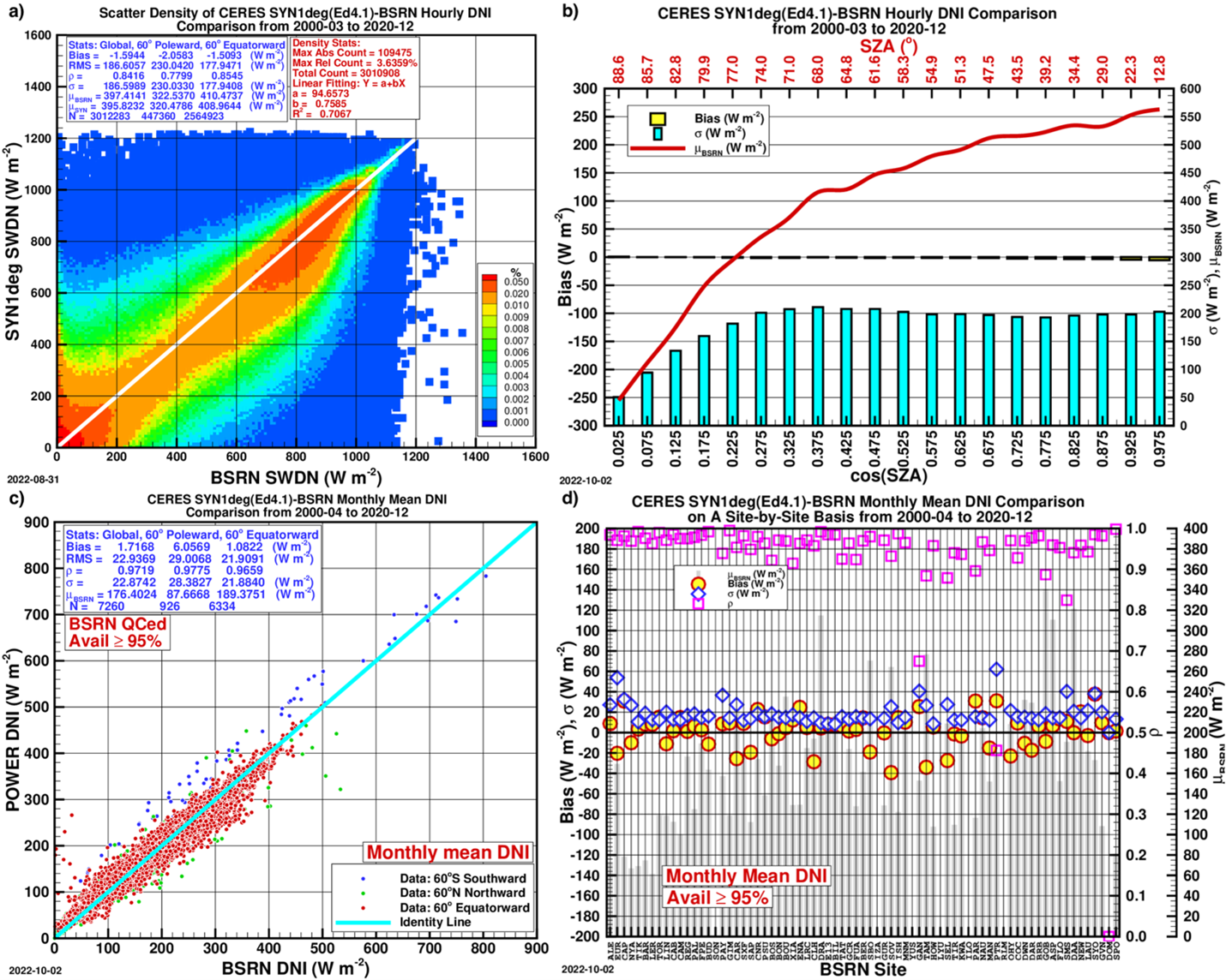
Figure 1. The CERES SYN1deg(Ed4.1) hourly DNI (labeled SWDN) after correction in comparison with the BSRN data. a) The scatter density plot. The comparison statistics are given for Global (all data points combined), 60° poleward, and 60° equatorward; σ stands for standard deviation, ρ for correlation coefficient, μBSRN for mean BSRN DNI, and μSYN for mean corrected DNI; b) Bias, σ and μBSRN in 20 equal-sized bins of cos(SZA); c) Scatter plot of monthly mean corrected DNI; d) Comparison on a site-by-site basis.
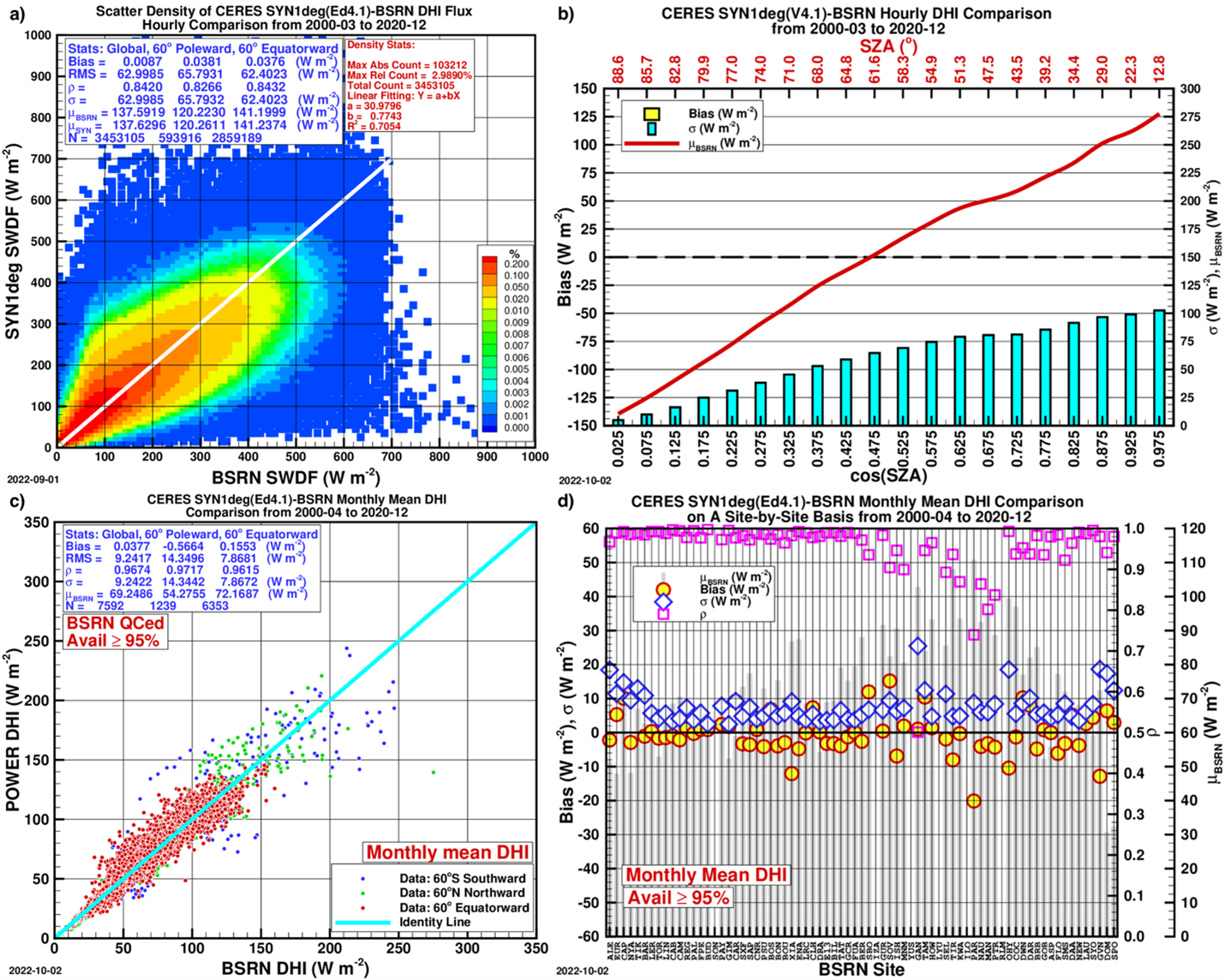
Figure 2. Same as Figure 1 except for corrected hourly DHI.
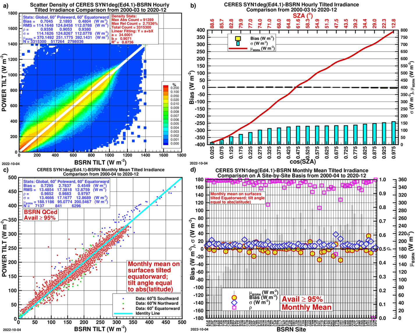
Figure 3. Same as Figure 1 except for GTI. At each site the surface is tilted equatorward, and the tilt angle is equal to the absolute value of its latitude.
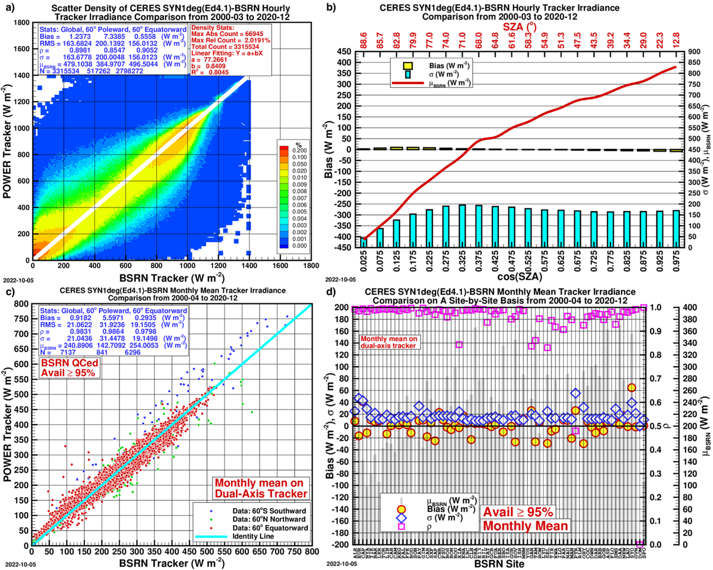
Figure 4. Same as Figure 1 except for GTrI on dual-axis trackers.
The Hourly irradiances on single-axis trackers
The dual-axis solar irradiance trackers can intercept the maximum possible solar irradiance, but the lower cost of equipment and maintenance of single-axis trackers make the latter more popular.
The available hourly GHI, DNI and DHI can be used to calculate the hourly global irradiance on various single-axis trackers on an hourly basis. Specifically, the system provides the hourly global irradiance for four typical kinds of single-axis tracker along with the hourly tilt angle 𝛽 and azimuth angle 𝛾 of the panel along with the rotation angle of the panel Ω relative to its axis. The rotation angle is used for active control of the panel.
This documentation uses the most popular east-north-up (ENU) local tangent plane coordinate system in which x-positive axis points to the east, y-positive axis points to the north, and z-positive axis points upward.
HSAT E-W
The horizontal single-axis tracker whose axis aligns with the east-west direction. The positive direction of the axis is assumed to point to the east, or the x-positive direction. Defining a positive direction of an axis makes it possible to determine the sign of the rotation angle. The right-hand rotation is defined as negative, and left-hand rotation positive. The tilt angle is equal to the absolute value of the rotation angle.
HSAT N-S
Horizontal single-axis tracker whose axis aligns with the north-south direction. The positive direction of the axis points to the north, or the y-positive axis. The tilt angle is also equal to the absolute value of the rotation angle.
PSAT
The polar single-axis tracker whose axis is parallel to the Earth’s rotation axis. An interesting feature of this configuration is that its rotation angle Ω is always equal to the hour angle 𝜔, and the incident angle of the direct sunlight is equal to that of the declination of the Sun everywhere. This means a PSAT always receives 91% or more of the direct sunlight.
VSAT
The vertical single-axis tracker whose axis is perpendicular to the horizontal ground. The positive direction of the VSAT is upward. The tilt angle of a VSAT is always 90°, and its rotation angle is always equal to the solar azimuth angle.
Since a single-axis tracker seeks to minimize the incident angle of the direct sunlight at any instant, one can evaluate its performance by investigating how much direct insolation it can receive in time and space. This calculation may clarify how the different kinds of single-axis trackers compare to each other at different latitudes.
More information about single-axis trackers is available in Zhang et al., (2025).
References
Zhang, T., Stackhouse, Jr., P.W., Macpherson, B., and Mikovitz, J.C., 2024a. A CERES-BasedDataset of Hourly DNI, DHI and Tilted Irradiance on Equatorward Tilted Surfaces: Derivation and Comparison with the Ground-Based BSRN Data. Solar Energy, 274 (2024) 112538. https://doi.org/10.1016/j.solener.2024.112538
Zhang, T., Stackhouse, Jr., P.W., Patadia, F., Aluru, N., Macpherson, B., and Mikovitz, J.C., 2025. A Vector-Based Universal Formula for the Solar Geometry of Single-Axis Trackers: Application to Five Typical Kinds and Their Performance at TOA and Surface in Time and Space. Solar Energy, 302 (2025) 114015. https://doi.org/10.1016/j.solener.2025.114015